Frame relay is a WAN technology that uses packet switching methodology for communication. A frame relay switch is required for configuring a frame relay network. The previous article on Configuring Frame Relay on Cisco Packet Tracer explains it on a simulator, in this article I’ll show how a Cisco router can be used as a frame relay switch. The same hub and spoke topology is used, only the Frame Relay switch router configuration is explained here refer the previous article for the Hub router and spoke routers configuration instructions.
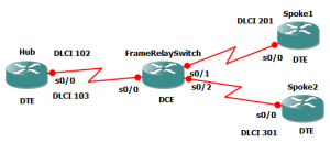
The Hub and Spoke network topology is shown below

As noted above the Hub and Spoke routers are DTEs and the FrameRelaySwitch Router is DCE. The commands are as follows
FrameRelaySwitch>enable

FrameRelaySwitch#configure terminal

FrameRelaySwitch(config)#frame-relay switching
FrameRelaySwitch(config)#interface serial 0/0

FrameRelaySwitch(config-if)#encapsulation frame-relay

FrameRelaySwitch(config-if)#frame-relay intf-type dce

FrameRelaySwitch(config-if)#clock rate 56000

FrameRelaySwitch(config-if)#frame-relay route 102 interface serial 0/1 201

FrameRelaySwitch(config-if)#frame-relay route 103 interface serial 0/2 301

FrameRelaySwitch(config-if)#no shutdown

FrameRelaySwitch(config-if)#exit
FrameRelaySwitch(config)#interface serial 0/1

FrameRelaySwitch(config-if)#encapsulation frame-relay

FrameRelaySwitch(config-if)#frame-relay intf-type dce

FrameRelaySwitch(config-if)#clock rate 56000

FrameRelaySwitch(config-if)#frame-relay route 201 interface serial 0/0 102

FrameRelaySwitch(config-if)#no shutdown

FrameRelaySwitch(config-if)#exit
FrameRelaySwitch(config)#interface serial 0/2

FrameRelaySwitch(config-if)#encapsulation frame-relay

FrameRelaySwitch(config-if)#frame-relay intf-type dce

FrameRelaySwitch(config-if)#clock rate 56000

FrameRelaySwitch(config-if)#frame-relay route 301 interface serial 0/0 103

FrameRelaySwitch(config-if)#no shutdown

FrameRelaySwitch(config-if)#exit
Now check the frame relay route by typing the following command in the privilege mode
FrameRelaySwitch#show frame-relay route
The following table is displayed
| Input Intf | Input Dlci | Output Intf | Output Dlci | Status |
|---|---|---|---|---|
| Serial0/0 | 102 | Serial0/1 | 201 | active |
| Serial0/0 | 103 | Serial0/2 | 301 | active |
| Serial0/1 | 201 | Serial0/0 | 102 | active |
| Serial0/2 | 301 | Serial0/0 | 103 | active |
Initially the status is shown as inactive because the Hub and Spoke routers are yet to be configured, after configuration the status must be active. Configure the Hub and Spoke routers as outlined in the previous article.

thanks jesin, that was exactly i was looking for