
I was going through the documentation of Cisco Packet Tracer when I read about the Modem Dial-up Utility. This utility was available on the Desktop tab of both PCs and Laptops.
The documentation said a PC/Laptop, Cloud and a router were required. It also mentioned that the router should have a user name authentication (username WORD password LINE) in addition to a modem interface.
The modem interface of the cloud must also have valid a phone number. But I didn’t know how to go about it. So googled for a long time and found this slideshare presentation. Starting from slide 17 it had the information I needed.
So I ended up writing this article on creating a Cisco Packet Tracer Dial Up dial up lab.
The topology we will be using is shown below.
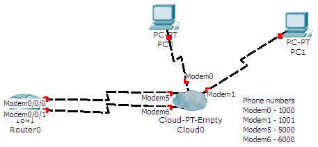 And here is the Cisco Packet Tracer Dial Up lab download link
Add the right modules
Turn off both the PCs, remove their default modules and place the PT-HOST-NM-1AM module. Turn them on.
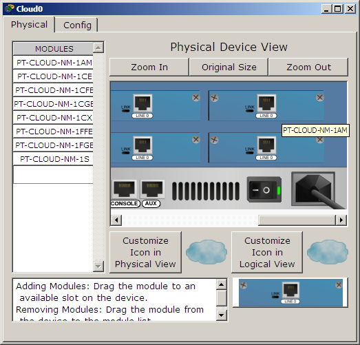
Turn off the cloud and place 4 PT-CLOUD-NM-1AM modules. The number of modules for the cloud depends on the number of PCs using the dial up utility. Double the number of PCs. Turn on the cloud now.
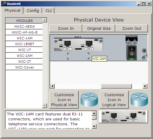
 Turn off the router and place a WIC-2AM module. Depending on the router you are using the following modules can be used
- WIC-1AM: Available for routers 1841, 2620XM, 2621XM and 2811. Has 1 RJ-11 port
- WIC-2AM: Available for routers 1841, 2620XM, 2621XM and 2811. Has 2 RJ-11 ports
- NM-8AM: Available for routers 2620XM, 2621XM and 2811. Has 8 RJ-11 ports
- PT-ROUTER-NM-1AM: Available for the Generic router only. Has 1 RJ-11 port
One port per dial up PC is required. Turn on the router.
 Connect all the devices as shown in the topology screenshot. Use the Phone cable from the Connections section.
Assign Phone numbers
Open the cloud, go to the config tab, select each Modem interface and assign a phone number. I’ll be using the following phone numbers.
| Interface | Phone number | Description |
|---|---|---|
| Modem0 | 1000 | Connected to PC0 |
| Modem1 | 1001 | Connected to PC1 |
| Modem5 | 5000 | Connected to router’s Modem0/0/0 interface |
| Modem6 | 6000 | Connected to router’s Modem0/0/1 interface |
It doesn’t matter what numbers are used on the interfaces connecting to the PCs. Make note of the phone numbers of interfaces connected to the router. These are the dial up numbers.
Configure IP addresses
We need to configure IP addresses in the the router’s modem interface. Click on the router and open the Config tab.
Hey wait a minute why are we going to the config tab? Why not open the CLI tab and do it with commands like a real Cisco pro?
You may do ahead a try but you’ll find that entering interface Modem0/0/0 will throw an Invalid input detected at .... error. So the only way of assigning IP addresses to the modem interfaces is through the Config tab.
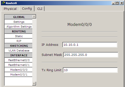 Once under the config tab click on a modem interface and assign an IP address and subnet mask. I’ll be using the following IP addresses.
| Interface | IP Address |
|---|---|
| Modem0/0/0 | 10.10.0.1 |
| Modem0/0/1 | 10.20.0.1 |
Configure DHCP on the router
The router needs to be a DHCP server to assign IP addresses to the dial up clients after a dial up connection is established. Open the CLI tab and configure two DHCP pools. One for each modem interface.
R1>enable
R1#configure terminal
R1(config)#ip dhcp pool dialup1
R1(dhcp-config)#network 10.10.0.0 255.255.255.0
R1(dhcp-config)#default-router 10.10.0.1
R1(dhcp-config)#ip dhcp pool dialup2
R1(dhcp-config)#network 10.20.0.0 255.255.255.0
R1(dhcp-config)#default-router 10.20.0.1
If you have more dial up clients more DHCP pools have to be configured.
Configure Authentication on the Router
Next is to configure a username/password combination. While a single credential is enough you may create as many as required.
R1(config)#username user1 password pwd1
Dial up from the PC
Open a PC, go to the desktop tab and click on the Dial up option.
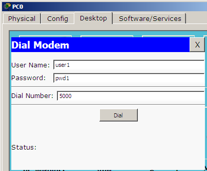 Fill the username, password, dial number fields and click the Dial button.
| Device | Username | Password | Dial Number |
|---|---|---|---|
| PC0 | user1 | pwd1 | 5000 |
| PC1 | user1 | pwd1 | 6000 |
A dial up session will be established and the link will light up. Now the PCs need to obtain IP addresses so click IP Configuration and choose DHCP on both the machines.
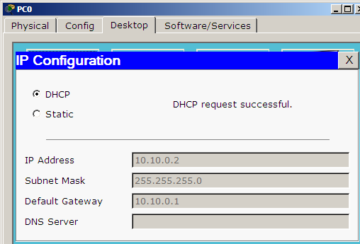 Now ping both PCs and use simulation mode to see how packets are flowing.
Download this Cisco Packet Tracer Dial Up lab.


Thanks Jesin! This was really useful
thanks for the clear explanation