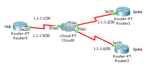
This article will explain frame relay configuration in Cisco Packet Tracer. Frame relay is a WAN technology. Read the Wikipedia article to learn more about Frame Relay. You can also try this on live routers and other network simulators, but the frame relay switch configuration varies. The setup here will use the hub and spoke configuration, Router0 is the hub, Router1 and Router2 are the spokes. Point-to-Point subinterfaces are created and PVCs (Permanent Virtual Circuits) are established between Router0 and Router1 and Router0 and Router2. So the Spoke routers communicate via Router0.
The topology of this lab is shown below
The DCE end of the serial cable should be connected to the frame relay switch.
Frame Relay Switch Configuration
Configure the serial interfaces of the Frame Relay switch as follows
Serial0
| DLCI | Name |
|---|---|
| 102 | R0-R1 |
| 103 | R0-R2 |
Serial1
| DLCI | Name |
|---|---|
| 201 | R1-R0 |
Serial2
| DLCI | Name |
|---|---|
| 301 | R2-R0 |
Select the frame relay tab and create the following links
| From Port | Sublink | To Port | Sublink |
|---|---|---|---|
| Serial0 | R0-R1 | Serial1 | R1-R0 |
| Serial0 | R0-R2 | Serial2 | R2-R0 |
Configure the routers
The configuration of each router is shown below
Router0 (Hub)
R0>enable

R0#configure terminal

R0(config)#interface Serial 2/0

R0(config-if)#no shutdown

R0(config-if)#encapsulation frame-relay

R0(config-if)#exit

R0(config)#interface Serial 2/0.102 point-to-point

R0(config-subif)#ip address 1.1.1.1 255.255.255.252

R0(config-subif)#frame-relay interface-dlci 102

R0(config-subif)#exit

R0(config)#interface Serial 2/0.103 point-to-point

R0(config-subif)#ip address 1.1.1.5 255.255.255.252

R0(config-subif)#frame-relay interface-dlci 103
Router1 (Spoke)
R1>enable

R1#configure terminal

R1(config)#interface Serial 2/0

R1(config-if)#no shutdown

R1(config-if)#encapsulation frame-relay

R1(config-if)#exit

R1(config)#interface Serial 2/0.201 point-to-point

R1(config-subif)#ip address 1.1.1.2 255.255.255.252

R1(config-subif)#frame-relay interface

R1(config-subif)#frame-relay interface-dlci 201
Router2 (Spoke)
R2>enable

R2#configure terminal

R2(config)#interface Serial 2/0

R2(config-if)#no shutdown

R2(config-if)#encapsulation frame-relay

R2(config-if)#exit

R2(config)#interface Serial 2/0.301 point-to-point

R2(config-subif)#ip address 1.1.1.6 255.255.255.252

R2(config-subif)#frame-relay interface-dlci 301
Configure routing on the spoke routers
Unless routing is configured the spoke routers cannot communicate among themselves. You can use any routing protocols. For this tutorial I will use static routing
Router1
R1(config)#ip route 1.1.1.4 255.255.255.252 1.1.1.1
Router2
R2(config)#ip route 1.1.1.0 255.255.255.252 1.1.1.5
Ping the routers to test connectivity among themselves.


Thank you……
Hi Jesin,
I found your tutorial really easy to understand .
However as I am a noob I am not able to create subinterfaces using the interface serial 0/0/1 command on R0 as hub and am using packet tracer .
Here is output of show run config>>
as soon as i try to create subinterface an error msg pops up
%cannot create subinterfaces on Se 0/0/1
Please help me out
Hi Sagar,
I think you missed out the keyword “point-to-point” in the interface command.
It should be
Let me know if it works.
You need to exit the interface config mode before executing the sub-into command. Command should be executed at the global config mode. Hope this helps.
However, the doing exactly what is done here, there is no connectivity between any of the routers via the frame relay network. Ping to the hub or the other spoke from either spoke isn’t reachable.
hi Jesin
Im trying to configure R0, the serial interface and i get % Invalid input detected at ‘^’ marker please help
Hi Nomsa,
Are you trying this on Packet Tracer, GNS3 or real hardware? Please post the commands.
HI Jesin,
thx for your tutorial btw.
i wan to ask is there any difference in doing in real hardware?
HI Jesin!
I tried to do all like in the the tutorial, but ping is not working.
I did my lab in PT.
R0# sh ip route
C 1.1.1.0 is directly connected, Serial2/0.102
C 1.1.1.4 is directly connected, Serial2/0.103
R0#sh run config
interface Serial2/0
no ip address
encapsulation frame-relay
!
interface Serial2/0.102 point-to-point
ip address 1.1.1.1 255.255.255.252
frame-relay interface-dlci 102
!
interface Serial2/0.103 point-to-point
ip address 1.1.1.5 255.255.255.252
frame-relay interface-dlci 103
R1#sh ip route
C 1.1.1.0 is directly connected, Serial2/0.201
S 1.1.1.4 [1/0] via 1.1.1.1
R1#sh run
interface Serial2/0
no ip address
encapsulation frame-relay
interface Serial2/0.201 point-to-point
ip address 1.1.1.2 255.255.255.252
frame-relay interface-dlci 201
R0#ping 1.1.1.2
Type escape sequence to abort.
Sending 5, 100-byte ICMP Echos to 1.1.1.2, timeout is 2 seconds:
…..
Success rate is 0 percent (0/5)
Thank you very much!
Hi Valentina,
The problem could be with the configuration of the Cloud device. Please check the settings in the “Frame Relay” and Interface sections of the cloud.
If everything is correct and it still doesn’t work share the PKT file over Dropbox (or another service) and I’ll have a look.
Hi brothers as I configured the above codes it doesn’t ping, and I didn’t understand what is 2/0.102 things. I am making just 0/0/0. Can anyone help me.
.102 is a (logical) subinterface